
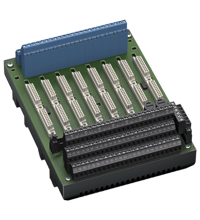
Excerpt from the datasheet: Technical data HiDTB08-SCT-99C-SC-RA
| Supply | ||
|---|---|---|
| Connection | X20: terminals 3, 5(+); 4, 6(-) | |
| Nominal voltage | 24 V DC, taking into account the rated voltage of the insulators used | |
| Voltage drop | 0.9V, voltage drop across the series diode on the terminal block must be taken into account. | |
| pulsation | ≤ 10% | |
| Merger | 2 A, in each case for 8 modules | |
| Power dissipation | ≤ 500 mW, without modules | |
| Reverse polarity protection | Yes | |
|
Redundancy |
||
| Supply | Redundancy is available. Power to the isolators is isolated, monitored, and protected by fuses. | |
|
Fault indication output |
||
| Connection | X20: terminals 1, 2 | |
| Output type | potential-free contact | |
| Switch behavior |
no fault: relay contact closed power supply failure: relay contact is open module failure: relay contact is open |
|
| Contact loading | 30 VDC, 1 A | |
|
Indicators/settings |
||
| Display elements |
LED PWR1 (terminal panel power supply), green LED LED PWR2 (terminal board power supply), green LED LED FAULT (fault indication), red LED - LED is on: module malfunction - LED blinking: power supply failure |
|
|
Compliance with the directive |
||
| Electromagnetic compatibility |
|
|
|
|
Directive 2014/30/EU | EN 61326-1:2013 (industrial premises) |
|
Correspondence |
||
| Electromagnetic compatibility |
NE 21:2017 For more information, see the system description. |
|
| Degree of protection | IEC 60529:2001 | |
|
Environmental conditions |
||
| Ambient temperature | -20 ... 60 °C (-4 ... 140 °F) | |
| Storage temperature | -40 ... 70 °C (-40 ... 158 °F) | |
|
Mechanical characteristics |
||
| Degree of protection | IP20 | |
| Connection |
|
|
|
|
Field side | hazardous area: 9 screw terminals per module, blue |
|
|
Control side | Non-hazardous area: 9 screw terminals per module, black |
|
|
Supply | removable screw terminals, black |
|
|
Malfunction output | removable screw terminals, black |
| Cross-section of the core | Screw terminals: 0.25–1.5 mm2 (24–12 AWG) | |
| Material | body: polycarbonate reinforced with 10% fiberglass | |
| weight | approx. 735 g | |
| Dimensions | 150 x 200 x 163 mm (5.9 x 7.9 x 6.42 in) (W x H x D) depth including module assembly | |
| Installation | on a 35 mm DIN rail in accordance with EN 60715:2001 | |
|
Data for use in hazardous areas |
||
| EC Type Examination Certificate | CESI 11 ATEX 062 | |
|
|
Marking |
 II (1)G [Ex ia Ga] IIC II (1)D [Ex ia Da] IIIC I (M1) [Ex ia Ma] I II (1)G [Ex ia Ga] IIC II (1)D [Ex ia Da] IIIC I (M1) [Ex ia Ma] I
|
| Safe zone |
|
|
|
|
Maximum safe voltage | 250 V (Note: U m is not the nominal voltage.) |
| Galvanic isolation |
|
|
|
|
Excitation circuit/control circuit | safe electrical insulation in accordance with IEC/EN 60079-11, peak voltage 375 V |
| Compliance with the directive |
|
|
|
|
Directive 2014/34/EU | EN IEC 60079-0:2018+AC:2020, EN 60079-11:2012, EN 50303:2000 |
|
International certificates |
||
| CSA approval |
|
|
|
|
Control drawing | see the control drawing of the corresponding modules |
| IECEx certification |
|
|
|
|
IECEx certificate | IECEx CES 11.0022 |
|
|
IECEx marking |
[Ex ia Ga] IIC [Ex ia Da] IIIC [Ex ia Ma] I |