
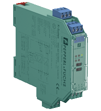
Technical specifications of the KFD2-SLD-Ex1.13100
| Main Features | ||
|---|---|---|
| Signal type | Digital output | |
|
Parameters related to functional safety |
||
| Safety Integrity Level (SIL) | SIL 3 | |
| Systematic ability (SC) | SC 3 | |
|
Supply |
||
| Connection | Power bus or terminals 14+, 15- | |
| Nominal voltage |
19 ... 30 V DC circuit-powered current |
|
| Input current | 115 mA at 24 V, 130 ohm load | |
| Power dissipation | 1.5 W at 24 V, 130 Ohm load | |
|
Entrance |
||
| Connection side | control side | |
| Connection |
Channel 1: terminals 7+, 8-, optional R ext between terminals 7 and 9 Channel 2: terminals 10+, 11-, optional R ext between terminals 10 and 12 |
|
| Input current |
OK. 6 mA at 24 V DC current If necessary, the current value can be increased using resistor Rext. |
|
| Signal level |
1-signal: 15 ... 30 VDC 0-signal: 0 ... 5 V DC |
|
|
Exit |
||
| Connection side | side of the field | |
| Connection |
channel 1: terminals 1+, 2-, 3 channel 2: terminals 4+, 5-, 6- |
|
| Internal resistor | approx. 64 ohms | |
| Current | type 100 mA | |
| Voltage | ≥ 13 V | |
| Current limit | 105 mA | |
| Open circuit voltage | type 19.2 V | |
| Load | nominal 0.08 ... 1 kOhm | |
| Switching frequency | Max. 2 Hz | |
| On/Off Delay | 30 ms / 30 ms | |
| Line fault detection |
signal at short circuit Rload < 30 Ohm, wire break Rload > 10 kOhm, test current < 4 mA pulse (20 ms on, 200 ms off) |
|
|
Galvanic isolation |
||
| Input/Power | basic insulation according to IEC/EN 61010-1, rated insulation voltage 60 V eff. | |
| Input/Input | basic insulation according to IEC/EN 61010-1, rated insulation voltage 60 V eff. | |
| Exit/Exit | basic insulation according to IEC/EN 61010-1, rated insulation voltage 60 V eff. | |
| Output/other circuits | Basic insulation according to IEC/EN 61010-1, rated insulation voltage 300 V eff. | |
|
Indicators/settings |
||
| Display elements | LEDs | |
| Controls | DIP switch | |
| Configuration | via DIP switches | |
| Marking | marking space at the front | |
|
Compliance with the directive |
||
| Electromagnetic compatibility |
|
|
|
|
Directive 2014/30/EU | EN 61326-1:2013 (industrial premises) |
|
Correspondence |
||
| Electromagnetic compatibility |
NE 21:2011 For more information, see the system description. |
|
| Degree of protection | IEC 60529:2001 | |
| Protection against electric shock | EN 61010-1:2010 | |
|
Environmental conditions |
||
| Ambient temperature | -20 ... 60 °C (-4 ... 140 °F) | |
|
Mechanical characteristics |
||
| Degree of protection | IP20 | |
| Connection | screw terminals | |
| weight | approx. 200 g | |
| Dimensions | 20 x 119 x 115 mm (0.8 x 4.7 x 4.5 in) (W x H x D), case type B2 | |
| Installation | on a 35 mm DIN rail in accordance with EN 60715:2001 | |
|
Data for use in hazardous areas |
||
| EU Type Examination Certificate | ECHA 17 ATEX 0076X | |
|
|
Marking |
 II 3(1)G Ex ec [ia IIB Ga] IIC T4 Gc II (1)D [Ex ia Da] IIIC I (M1) [Ex ia Ma] I II 3(1)G Ex ec [ia IIB Ga] IIC T4 Gc II (1)D [Ex ia Da] IIIC I (M1) [Ex ia Ma] I
|
|
|
Voltage | 22.2 V |
|
|
Current | 360 mA |
|
|
Power | 1990 MW |
| Supply |
|
|
|
|
Maximum safe voltage | 60 V (Caution! Nominal voltage may be lower.) |
| Entrance |
|
|
|
|
Maximum safe voltage | 60 V (Caution! Nominal voltage may be lower.) |
| Galvanic isolation |
|
|
|
|
Exit/Exit | safe electrical insulation in accordance with IEC/EN 60079-11, peak voltage value 60 V |
|
|
Output/other circuits | safe electrical insulation in accordance with IEC/EN 60079-11, peak voltage 375 V |
| Compliance with the directive |
|
|
|
|
Directive 2014/34/EU | EN IEC 60079-0:2018+AC:2020, EN 60079-7:2015+A1:2018, EN 60079-11:2012 |
|
International certificates |
||
| IECEx certification |
|
|
|
|
IECEx Certificate | IECEx EXA 17.0019X |
|
|
IECEx marking |
Ex ec [ia IIB Ga] IIC T4 Gc [Ex ia Da] IIIC [Ex ia Ma] I |