
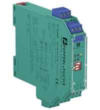
Technical characteristics of the KFD2-SR2-Ex2.W.SM
| Main Features | ||
|---|---|---|
| Signal type | Digital input | |
| Programming | using a DIP switch and programmable | |
|
Parameters related to functional safety |
||
| Safety Integrity Level (SIL) | SIL 2 | |
|
Supply |
||
| Connection | Power bus or terminals 14+, 15- | |
| Nominal voltage | 20 ... 30 V DC | |
| Power consumption | Max 1.5 W | |
|
Entrance |
||
| Connection side | side of the field | |
| Connection |
Input I: terminals 1+, 2+, 3-; Input II: terminals 4+, 5+, 6- |
|
| Nominal values | according to EN 60947-5-6 (NAMUR) | |
| Open circuit voltage/short circuit current | approx. 8 VDC / approx. 8 mA | |
| Switching point/switching hysteresis | 1.2 ... 2.1 mA / approx. 0.2 mA | |
| Line fault detection | open circuit I ≤ 0.1 mA, short circuit I > 6 mA | |
| Control input | sensor power supply approx. 8.2 V, resistance 1.2 kOhm | |
| Pulse duration |
> 200 µs for idle state control, > 250 µs to determine the direction of rotation |
|
|
Exit |
||
| Connection side | control side | |
| Connection | output I: terminals 7, 8, 9; output II: terminals 10, 11, 12 | |
| Contact loading | 250VAC/2A/cos φ>0.75; 126.5VAC/4A/cos φ>0.75; 40VDC/2A resistive load | |
| Minimum switching current | 2 mA / 24 V DC current | |
| On/Off Delay | OK. 20ms / approx. 20 ms | |
| Mechanical life | 10 7 switching cycles | |
| Cost of the trip |
to control the state of rest: 0.1 Hz; 0.5 Hz; 2 Hz; 10 Hz adjustable via DIP switch (S1 and S2) |
|
|
Transmission characteristics |
||
| Accuracy | 5% (S3 = I), 30% (S3 = II) | |
| Overriding the launch | 5 seconds or 20 seconds, programmable | |
| Frequency range | ≤ 2 kHz | |
| Detecting the direction of rotation | Phase difference 90° between pulse input signals 1 and 2, overlap ≥ 125 µs | |
|
Galvanic isolation |
||
| Input, output | reinforced insulation according to IEC/EN 61010-1, rated insulation voltage 300 V eff. | |
| Input/Power | reinforced insulation according to IEC/EN 61010-1, rated insulation voltage 300 V eff. | |
| Output/Power | reinforced insulation according to IEC/EN 61010-1, rated insulation voltage 300 V eff. | |
| Exit/Exit | reinforced insulation according to IEC/EN 61010-1, rated insulation voltage 300 V eff. | |
|
Indicators/settings |
||
| Display elements | LEDs | |
| Controls | DIP switch | |
| Configuration | via DIP switches | |
| Marking | marking space at the front | |
|
Compliance with the directive |
||
| Electromagnetic compatibility |
|
|
|
|
Directive 2014/30/EU | EN 61326-1:2013 (industrial premises) |
| Low voltage |
|
|
|
|
Directive 2014/35/EU | EN 61010-1:2010 |
|
Correspondence |
||
| Electromagnetic compatibility | NE 21:2006 | |
| Degree of protection | IEC 60529:2001 | |
| Entrance | EN 60947-5-6:2000 | |
|
Environmental conditions |
||
| Ambient temperature | -20 ... 60 °C (-4 ... 140 °F) | |
|
Mechanical characteristics |
||
| Degree of protection | IP20 | |
| Connection | screw terminals | |
| weight | approx. 150 g | |
| Dimensions | 20 x 119 x 115 mm (0.8 x 4.7 x 4.5 in) (W x H x D), case type B2 | |
| Installation | on a 35 mm DIN rail in accordance with EN 60715:2001 | |
|
Data for use in hazardous areas |
||
| EU Type Examination Certificate | PTB 00 ATEX 2080 | |
|
|
Marking |
 II (1)G [Ex ia Ga] IIC II (1)D [Ex ia Da] IIIC I (M1) [Ex ia Ma] I II (1)G [Ex ia Ga] IIC II (1)D [Ex ia Da] IIIC I (M1) [Ex ia Ma] I
|
|
|
Entrance | Ex iа |
|
|
Voltage | 10.5 V |
|
|
Current | 13 mA |
|
|
Power | 34 mW (linear characteristic) |
| Supply |
|
|
|
|
Maximum safe voltage | 253 VAC / 125 VDC (Note: U m is not the nominal voltage.) |
| Exit |
|
|
|
|
Maximum safe voltage | 253 VAC (Caution: Nominal voltage may be lower.) |
| Fault indication output |
|
|
|
|
Maximum safe voltage | 40 VDC (Note: U m is not the nominal voltage.) |
| Certificate | TUV 99 ATEX 1493 X | |
|
|
Marking |
II 3G Ex ec nC IIC T4 Gc
|
| Exit |
|
|
|
|
Contact loading | 50VAC/4A/cos φ>0.7; 40VDC/2A resistive load |
| Galvanic isolation |
|
|
|
|
Input, output | safe electrical insulation in accordance with IEC/EN 60079-11, peak voltage 375 V |
|
|
Input/Power | safe electrical insulation in accordance with IEC/EN 60079-11, peak voltage 375 V |
| Compliance with the directive |
|
|
|
|
Directive 2014/34/EU | EN IEC 60079-0:2018+AC:2020, EN 60079-7:2015+A1:2018, EN 60079-11:2012, EN IEC 60079-15:2019 |
|
International certificates |
||
| FM approval |
|
|
|
|
FM certificate | FM19US0207X |
|
|
Control drawing | 116-0035 |
| UL approval | E106378 | |
|
|
Control drawing | 116-0145 |
|
|
Contact loading | 250VAC/2A/cos φ>0.75; 126.5VAC/4A/cos φ>0.75; 30VDC/2A resistive load |
| CSA approval |
|
|
|
|
Control drawing | 116-0047 |
| IECEx certification |
|
|
|
|
IECEx Certificate | IECEx PTB 11.0034, IECEx TUN 19.0013X |
|
|
IECEx marking |
[Ex ia Ga] IIC [Ex ia Da] IIIC [Ex ia Ma] I Ex ec nC IIC T4 Gc |