
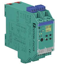
Technical specifications of the KFU8-UFT-Ex2.D
| Main Features | ||
|---|---|---|
| Signal type | Digital input | |
|
Supply |
||
| Connection | terminals 23, 24 | |
| Nominal voltage | 20 ... 90 VDC / 48 ... 253 VAC 50 ... 60 Hz | |
| Rated current | approx. 130 mA | |
| Power dissipation | 2.2 W / 3.5 VA | |
| Power consumption | 2.5 W / 5 VA | |
|
Interface |
||
| Programming interface | programming connector | |
|
Entrance |
||
| Connection side | side of the field | |
| Connection |
input I: terminals 1+, 3- input II: terminals 4+, 6- input III: terminals 13+, 14- (control input 1) input IV: terminals 15+, 14- (control input 2) |
|
| Entrance I, II | 2-wire sensor, sensor according to EN 60947-5-6 (NAMUR) or mechanical contact | |
|
|
Open circuit voltage/short circuit current | 8.2 V / 10 mA |
|
|
Pulse duration | min. 250 µs, rotation direction signal overlap: ≥ 125 µs |
|
|
Input frequency | rotation direction control 0.001 ... 1000 Hz slip control 10 ... 1000 Hz |
|
|
Line fault detection | open circuit I ≤ 0.15 mA; short circuit I > 6.5 mA |
| Entrance III, IV |
|
|
|
|
Active passive | I > 4 mA (min. 100 ms) / I < 1.5 mA |
|
|
Open circuit voltage/short circuit current | 18 V / 5 mA |
|
Exit |
||
| Connection side | control side | |
| Connection |
output I: terminals 10, 11, 12 output II: terminals 16, 17, 18 output III: terminals 19+, 20- output IV: terminals 21+, 20- output V: terminals 7-, 8+ |
|
| Exit I, II | signal, relay | |
|
|
Contact loading | 250 V AC / 2 A / cos φ ≥ 0.7; 40 V DC / 2 A |
|
|
Mechanical life | 5 x 10 7 switching cycles |
|
|
On/Off Delay | OK. 20ms / approx. 20 ms |
| Exit III and IV | signal, electronic output, passive | |
|
|
Contact loading | 40 V DC |
|
|
Signal level |
1-signal: (L+) -2.5V (50mA, short circuit/overload protection) 0-signal: off (off-state current ≤ 10 μA) |
| Exit B | analogue | |
|
|
Current range | 0...20 mA or 4...20 mA |
|
|
Open circuit voltage | Max 24V DC |
|
|
Load | Max. 650 Ohm |
|
|
Malfunction signal | lower limit I ≤ 3.6 mA, upper limit I ≥ 21.5 mA (according to NAMUR NE43) |
|
Transmission characteristics |
||
| Entrance I and II |
|
|
|
|
Measurement range | 0.001...1000 Hz |
|
|
Permission | slip control: 1% frequency measurement: 0.1% of the measured value; but >0.001 Hz |
|
|
Accuracy | slip control: 1% frequency measurement: 0.5% of the measured value; but >0.001 Hz |
|
|
Measuring time | frequency measurement: < 100 ms |
|
|
The influence of ambient temperature | 0.003%/K (30 ppm) |
| Exit I, II |
|
|
|
|
Delayed response | ≤ 200 ms |
| Exit B |
|
|
|
|
Permission | < 10 μA |
|
|
Accuracy | < 30 μA |
|
|
The influence of ambient temperature | 0.005%/K (50 ppm) |
| Accuracy | 0.1% | |
|
Galvanic isolation |
||
| Input I, II/other circuits | reinforced insulation according to IEC/EN 61010-1, rated insulation voltage 300 V eff. | |
| Input III, IV/power | reinforced insulation according to IEC/EN 61010-1, rated insulation voltage 300 V eff. | |
| Output I, II/other circuits | reinforced insulation according to IEC/EN 61010-1, rated insulation voltage 300 V eff. | |
| Mutual output I, II, III | reinforced insulation according to IEC/EN 61010-1, rated insulation voltage 300 V eff. | |
| Mutual output I, II, IV | reinforced insulation according to IEC/EN 61010-1, rated insulation voltage 300 V eff. | |
| Output III, IV/power supply | reinforced insulation according to IEC/EN 61010-1, rated insulation voltage 300 V eff. | |
| Output III, IV/Input III, IV | basic insulation according to IEC/EN 61010-1, rated insulation voltage 50 V eff. | |
| Exit III, IV/V | basic insulation according to IEC/EN 61010-1, rated insulation voltage 50 V eff. | |
| Output voltage/power supply | reinforced insulation according to IEC/EN 61010-1, rated insulation voltage 300 V eff. | |
| Interface/power | reinforced insulation according to IEC/EN 61010-1, rated insulation voltage 300 V eff. | |
| Interface/output III, IV | basic insulation according to IEC/EN 61010-1, rated insulation voltage 50 V eff. | |
|
Indicators/settings |
||
| Display elements | LEDs, display | |
| Controls | Control Panel | |
| Configuration |
using the control buttons using PACTware |
|
| Marking | marking space at the front | |
|
Compliance with the directive |
||
| Electromagnetic compatibility |
|
|
|
|
Directive 2014/30/EU | EN 61326-1:2013 (industrial premises) |
| Low voltage |
|
|
|
|
Directive 2014/35/EU | EN 61010-1:2010 |
|
Correspondence |
||
| Electromagnetic compatibility | NE 21:2006 | |
| Degree of protection | IEC 60529:2001 | |
| Entrance | EN 60947-5-6:2000 | |
|
Environmental conditions |
||
| Ambient temperature | -20 ... 60 °C (-4 ... 140 °F) | |
|
Mechanical characteristics |
||
| Degree of protection | IP20 | |
| Connection | screw terminals | |
| weight | 300 g | |
| Dimensions | 40 x 119 x 115 mm (1.6 x 4.7 x 4.5 in) (W x H x D), case type C2 | |
| Installation | on a 35 mm DIN rail in accordance with EN 60715:2001 | |
|
Data for use in hazardous areas |
||
| EU Type Examination Certificate | TUV 99 ATEX 1471 | |
|
|
Marking |
 II (1)G [Ex ia Ga] IIC II (1)D [Ex ia Da] IIIC I (M1) [Ex ia Ma] I II (1)G [Ex ia Ga] IIC II (1)D [Ex ia Da] IIIC I (M1) [Ex ia Ma] I
|
| Supply |
|
|
|
|
Maximum safe voltage | 253 VAC / 125 VDC (Note: U m is not the nominal voltage.) |
| Entrance I and II | terminals 1+, 3-; 4+, 6-: Ex ia | |
|
|
Voltage U o | 10.1 V |
|
|
Current I o | 13.5 mA |
|
|
Power P o | 34 mW (linear characteristic) |
| Entrance III and IV | terminals 13+, 14-; 15+, 14- are not intrinsically safe | |
|
|
Maximum safe voltage U m | 40 V (Note: U m is not the nominal voltage.) |
| Exit I, II | terminals 10, 11, 12; 16, 17, 18 are not intrinsically safe | |
|
|
Maximum safe voltage | 253 V (Caution! Nominal voltage may be lower.) |
|
|
Contact loading |
253 V AC/2 A/cos φ > 0.7; 40 V DC/2 A resistive load (TÜV 99 ATEX 1471) |
| Exit III and IV | terminals 19, 20, 21 are not intrinsically safe | |
|
|
Maximum safe voltage U m | 40 V (Note: U m is not the nominal voltage.) |
| Exit B | terminals 8+, 7- are not intrinsically safe | |
|
|
Maximum safe voltage U m | 40 VDC (Note: U m is not the nominal voltage.) |
| Interface | 232 rupees | |
|
|
Maximum safe voltage | 40 V (Note: U m is not the nominal voltage.) |
| Galvanic isolation |
|
|
|
|
Input I, II/other circuits | safe electrical insulation in accordance with IEC/EN 60079-11, peak voltage 375 V |
| Compliance with the directive |
|
|
|
|
Directive 2014/34/EU | EN IEC 60079-0:2018, EN 60079-11:2012 |
|
International certificates |
||
| FM approval |
|
|
|
|
Control drawing | 16-538FM-12 |
| IECEx certification |
|
|
|
|
IECEx Certificate | IECEx TUN 04.0007 |
|
|
IECEx marking | [Ex ia Ga] IIC, [Ex ia Da] IIIC, [Ex ia Ma] I |