
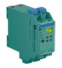
Technical data of the KFD2-HLC-Ex1.D.4S
| Main Features | ||
|---|---|---|
| Signal type | Analog input | |
| Supply | ||
| Connection | Power bus or terminals 23+, 24- | |
| Nominal voltage | 19...30 V DC | |
| Rated current | approx. 140 mA at 24 VDC | |
| Power dissipation | 2.7 W | |
| Power consumption | 3.3 W | |
| HART signal channels (intrinsically safe) | ||
| Correspondence | HART Field Device Input (Versions 5-7) | |
| Interface | ||
| Programming interface | programming connector | |
| Entrance | ||
| Connection side | side of the field | |
| Connection | terminals 1, 2, 3, 4, 5, 6 | |
| Open circuit voltage/short circuit current | type 24 V/28 mA | |
| Input impedance | 250 Ohm, 5% (terminals 2, 3 and with jumper 5, 6) | |
| Available voltage | ≥ 15.5 V at 20 mA, short circuit protection | |
| Exit | ||
| Connection side | control side | |
| Connection |
output I: terminals 10, 11, output II: terminals 11, 12, output III: terminals 16, 17, output IV: terminals 17, 18 output V: terminals 7, 8, 9, output VI: terminals 13, 14, 15, output VII: terminals 19, 20, 21 |
|
| Exit I, II, III, IV |
|
|
|
|
Output signal | relay and yellow LED |
|
|
Mechanical life | 10 7 switching cycles |
|
|
On/Off Delay | OK. 20ms / approx. 20 ms |
| Exit V, VI, VII |
|
|
|
|
Output signal | analog |
|
|
Current range | 4 ... 20 mA (source or sink mode) |
|
|
Load | Max 650 Ohm, Source Mode |
|
|
Voltage range | 5...30 V, drain mode from external power source |
|
|
Malfunction signal | decrease in scale I ≤ 2 mA, increase in I ≥ 21.5 mA (according to NAMUR NE43) or maintaining the measured value |
| Other results | HART communicator on terminals 22, 24 | |
| Collective error message | Power bus and red LED | |
| Transfer characteristics | ||
| Exit V, VI, VII |
|
|
|
|
Permission | Max. 2 µA |
|
|
Accuracy | < 20 µA, 10 µA typ. |
|
|
The influence of ambient temperature | < ± 2 μA/K |
|
|
Measurement duration/response latency | HART message acquisition time plus 100 ms |
| Relay | programmable to either fault value or trip value (with direction, hysteresis and delay) | |
| Galvanic isolation | ||
| Exit I, II/III, IV | Functional insulation according to IEC 62103, rated insulation voltage 250 V eff. | |
| Output I, II, III, IV/other circuits | Reinforced insulation according to IEC 62103, rated insulation voltage 300 V r.m.s. | |
| Output V/VI/VII/power supply | Functional insulation according to IEC 62103, rated insulation voltage 50 V eff. | |
| Indicators/settings | ||
| Display elements | LEDs, display | |
| Controls | Control Panel | |
| Configuration |
using the control buttons via PACTware |
|
| Marking | marking space at the front | |
| Compliance with directives | ||
| Electromagnetic compatibility |
|
|
|
|
Directive 2014/30/EU | EN 61326-1:2013 (industrial premises) |
| Low voltage |
|
|
|
|
Directive 2014/35/EU | EN 61010-1:2010 |
| Correspondence | ||
| Electromagnetic compatibility | NE 21:2006 | |
| Degree of protection | IEC 60529:2001 | |
| Environmental conditions | ||
| Ambient temperature | -20...60°С (-4...140°F) | |
| Mechanical characteristics | ||
| Degree of protection | IP20 | |
| Connection | screw terminals | |
| Weight | 300 g | |
| Dimensions | 40 x 119 x 115 mm (1.6 x 4.7 x 4.5 in) (W x H x D), case type C2 | |
| Installation | on a 35 mm DIN mounting rail in accordance with EN 60715:2001 | |
| Data for use in hazardous areas | ||
| EU type inspection certificate | BASEEFA 07 ATEX 0174 | |
|
|
Marking |
 II (1)G [Ex ia Ga] IIC II (1)D [Ex ia Da] IIIC II (1)G [Ex ia Ga] IIC II (1)D [Ex ia Da] IIIC
|
| Supply |
|
|
|
|
Maximum safe voltage | 253 VAC (Caution: Nominal voltage may be lower.) |
| Equipment | terminals 1, 4/3 (with connection between terminals 4 and 5) | |
|
|
Voltage | 25.2 V |
|
|
Current | 104.9 mA |
|
|
Power | 0.661 W |
|
|
Internal capacity | 1.1 nF |
|
|
Internal inductance | 0 mH |
| Equipment | terminals 2, 5/3 | |
|
|
Voltage | < 28 V |
|
|
Power | < 1.33 W |
|
|
Voltage | 1.1 V |
|
|
Current | 11.9 mA |
|
|
Power | 4 mW |
|
|
Internal capacity | 0 μF |
|
|
Internal inductance | 0 mH |
| Exit I, II, III, IV | terminals 10, 11; 11, 12; 16, 17; 17, 18, non-intrinsically safe | |
|
|
Maximum safe voltage | 253 V (Note: U m is not the nominal voltage.) |
|
|
Contact loading |
253 V AC/1 A/cos φ > 0.7; 30 V DC/1 A resistive load (BASEEFA 07 ATEX 0174) 50 VAC/1 A/cos φ > 0.7; Resistive load 30 VDC/1 A (Pepperl+Fuchs self-declaration) |
| Exit V, VI, VII | terminals 7, 8, 9; 13, 14, 15; 19, 20, 21, non-intrinsically safe | |
|
|
Maximum safe voltage | 253 V (Note: U m is not the nominal voltage.) |
| Certificate | PF 07 CERT 1141 X | |
|
|
Marking |
II 3G Ex nA nC IIC T4 Gc
|
| Galvanic isolation |
|
|
|
|
Input/Other circuits | safe electrical insulation in accordance with IEC/EN 60079-11, peak voltage 375 V |
| Compliance with directives |
|
|
|
|
Directive 2014/34/EU | EN IEC 60079-0:2018+AC:2020, EN 60079-11:2012, EN 60079-15:2010 |
| International approvals | ||
| FM approval |
|
|
|
|
Control drawing | 116-0129 |
| IECEx approval |
|
|
|
|
IECEx certificate | IECEx BAS 07.0047 |
|
|
IECEx marking | [Ex ia Ga] IIC, [Ex ia Da] IIIC |