
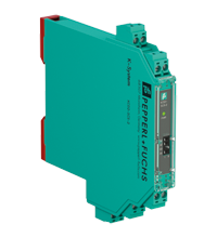
Technical data of KCD2-SCS-2
| Main Features | ||
|---|---|---|
| Signal type | Analog input/analog output | |
| Parameters related to functional safety | ||
| Safety Integrity Level (SIL) | SIL 2 | |
| Systematic Capabilities (SC) | SC 3 | |
| Supply | ||
| Connection | Power bus or terminals 9+, 10- | |
| Nominal voltage | 19...30 V DC | |
| Pulsation | Max. 10% | |
| Rated current | Max. 88 mA at 24 V | |
| Power dissipation | Max 1.4 W | |
| Power consumption | Max. 2.1 W | |
| Analog input | ||
| Number of channels | 2 | |
| Suitable field devices | 2-wire SMART transmitters | |
| Signal | 0/4...20 mA, limited to approx. 30 mA | |
| Field circuit | terminals 1+, 2-, 3+, 4- | |
| Available voltage |
min. 15 V at 20 mA min. 18 V at 4 mA |
|
| Control circuit | terminals 5-, 6+; 7-, 8+ | |
| Input voltage |
The voltage at the terminals is 10...30 V. If the current is supplied from a source > 24 V, a series resistance of ≥ (V - 24)/0.02 Ohm is required, where V is the source voltage. The maximum resistance value is (V - 10)/0.02 Ohm. (drain output) |
|
| Load | Max 350 Ohm (Source Output) | |
| Pulsation | 20 mV eff. | |
| Analog output | ||
| Number of channels | 2 | |
| Suitable field devices | SMART I/P converters (positioners), local displays | |
| Signal | 0/4...20 mA, limited to approx. 30 mA | |
| Field circuit | terminals 1+, 2-, 3+, 4- | |
| Load | Max. 650 Ohm | |
| Voltage | min. 13 V at 20 mA | |
| Pulsation | 20 mV eff , on all signal terminals | |
| Control circuit | terminals 5-, 6+; 7-, 8+ | |
| Voltage drop | Max 6 V | |
| Line fault detection | > 100 kOhm at max 30 V, with open wiring | |
| Transfer characteristics | ||
| Deviation | Max. 20 µA incl. calibration, linearity, hysteresis, loads, and supply voltage variations | |
|
|
The influence of ambient temperature | < 2 µA/K (-40...70 °C (-40...158 °F)) |
| Frequency range |
from the field side to the control side: bandwidth with a signal swing of 0.5 V 0 ... 3 kHz (-3 dB) from the control side to the field side: bandwidth with a signal swing of 0.5 V 0 ... 3 kHz (-3 dB) |
|
| Settlement time | Max. 200 ms | |
| Rise time/fall time | Max. 100 ms (10...90%) | |
| Galvanic isolation | ||
| Excitation circuit/control circuit | Basic insulation according to IEC/EN 61010-1, rated insulation voltage 300 V eff. | |
| Control circuit/control circuit | functional insulation, rated voltage: 50 V | |
| Field circuit/power supply | reinforced insulation according to IEC/EN 61010-1, rated insulation voltage 300 V eff. | |
| Control/Power | Basic insulation according to IEC/EN 61010-1, rated insulation voltage 300 V eff. | |
| Indicators/settings | ||
| Display elements | LED | |
| Configuration | via DIP switches | |
| Marking | marking space at the front | |
| Compliance with directives | ||
| Electromagnetic compatibility |
|
|
|
|
Directive 2014/30/EU | EN 61326-1:2013 (industrial premises) |
| Correspondence | ||
| Electromagnetic compatibility |
NE 21:2017 EN 61326-3-2:2018 |
|
| Degree of protection | IEC 60529 | |
| Environmental conditions | ||
| Ambient temperature | -40...70°С (-40...158°F) | |
| Mechanical characteristics | ||
| Degree of protection | IP20 | |
| Connection | screw terminals | |
| Weight | approx. 115 g | |
| Dimensions | 12.5 x 124 x 114 mm (0.5 x 4.9 x 4.5 in) (W x H x D), case type A2 | |
| Installation | on a 35 mm DIN mounting rail in accordance with EN 60715:2001 | |