
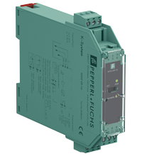
Technical characteristics of the KFD2-ER-1.6
| Main Features | ||
|---|---|---|
| Signal type | Digital input | |
|
Supply |
||
| Connection | Power bus or terminals 11+, 12- | |
| Nominal voltage | 20 ... 30 V DC | |
|
Entrance |
||
| Connection side | side of the field | |
| Connection | terminals 1 (ground), 2 (min), 3 (max) | |
| Open circuit voltage/short circuit current | approx. 10 V AC (approx. 1 Hz) / approx. 5 mA | |
| Control input |
min Max. control system: terminals 1, 2, 3 On/Off system: terminals 1, 3 |
|
| Response sensitivity | 5...150 kOhm, adjustable with a potentiometer (20 turns) | |
|
Exit |
||
| Connection side | control side | |
| Connection | terminals 7, 8, 9 | |
| Exit | 1 changeover contact | |
| Contact loading | 253VAC/2A/cos φ>0.7; 40VDC/2A resistive load | |
| On/Off Delay | approx. 1 sec / approx. 1 sec | |
|
Galvanic isolation |
||
| Input, output | reinforced insulation according to IEC/EN 61010-1, rated insulation voltage 300 V eff. | |
| Input/Power | reinforced insulation according to IEC/EN 61010-1, rated insulation voltage 300 V eff. | |
| Output/Power | reinforced insulation according to IEC/EN 61010-1, rated insulation voltage 300 V eff. | |
|
Indicators/settings |
||
| Display elements | LEDs | |
| Controls |
DIP switch potentiometer |
|
| Configuration |
using DIP switches: switch S1 Position I no-load current: In the no-load current principle, the relay becomes active when the limit is reached. Position II closed-circuit current: In closed-circuit current mode, the relay is activated when power is applied. The relay is deactivated when the limit is reached. via a potentiometer |
|
| Marking | marking space at the front | |
|
Compliance with the directive |
||
| Electromagnetic compatibility |
|
|
|
|
Directive 2014/30/EU | EN 61326-1:2013 (industrial premises) |
| Low voltage |
|
|
|
|
Directive 2014/35/EU | EN 61010-1:2010 |
|
Correspondence |
||
| Electromagnetic compatibility | NE 21:2006 | |
| Degree of protection | IEC 60529:2001 | |
|
Environmental conditions |
||
| Ambient temperature |
-20 ... 60 °C (-4 ... 140 °F) Extended ambient temperature range up to 70°C (158°F), see manual for installation requirements |
|
|
Mechanical characteristics |
||
| Degree of protection | IP20 | |
| Connection | screw terminals, max 2.5 mm2 | |
| weight | approx. 110 g | |
| Dimensions | 20 x 107 x 115 mm (0.8 x 4.2 x 4.5 in) (W x H x D), case type B1 | |
| Installation | on a 35 mm DIN rail in accordance with EN 60715:2001 | |