
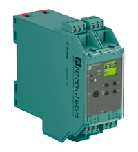
Technical data of the KFD2-GUT-1.D
| Main Features | ||
|---|---|---|
| Signal type | Analog input | |
| Parameters related to functional safety | ||
| Safety Integrity Level (SIL) | SIL 2 | |
| Supply | ||
| Connection | terminals 23+, 24- or power supply module/power bus | |
| Nominal voltage | 20...30 V DC | |
| Rated current | approx. 100 mA | |
| Power dissipation/power consumption | ≤ 2 W / 2.2 W | |
| Interface | ||
| Programming interface | programming connector | |
| Entrance | ||
| Connection side | side of the field | |
| Connection |
terminals 1, 2, 3, 4, 6 |
|
| RTD | Pt100, Pt500, Pt1000, Ni100, Ni1000 | |
|
|
Current measurement | approx. 400 µA |
|
|
Types of measurements | 2-, 3-, 4-wire technology |
|
|
Lead resistance | Max. 50 Ohm |
|
|
Monitoring the measuring circuit | sensor failure, sensor short circuit |
| Thermocouples | type B, E, J, K, L, N, R, S, T (IEC 584-1: 1995) | |
|
|
Cold junction compensation | external and internal |
|
|
Monitoring the measuring circuit | sensor failure |
| Potentiometer | 0.8...20 kOhm | |
|
|
Types of measurements | 2-, 3-, 5-wire technology |
| Voltage | 0...10 V, 2...10 V, 0...1 V, -100...100 mV | |
| Open circuit voltage | Max 5V with resistance measurement sensor | |
| Input impedance |
≥ 250 kOhm (0...10 V) min. 1 MOhm (0...1 V, -100...100 mV) |
|
| Exit | ||
| Connection side | control side | |
| Connection |
output I: terminals 10, 11, 12 output II: terminals 16, 17, 18 output III: terminals 8+, 7- |
|
| Exit I, II | relay | |
|
|
Contact loading | 250 V AC / 2 A / cos φ ≥ 0.7; 40 V DC / 2 A |
|
|
Mechanical life | 5 x 10 7 switching cycles |
|
|
On/Off Delay | OK. 20ms / approx. 20 ms |
| Result III | Analog current output | |
|
|
Current range | 0...20 mA or 4...20 mA |
|
|
Open circuit voltage | Max 24V DC |
|
|
Load | Max. 650 Ohm |
|
|
Malfunction signal | lower limit I ≤ 3.6 mA, upper limit I ≥ 21 mA (according to NAMUR NE43) |
| Collective error message | Power bus | |
| Transfer characteristics | ||
| Deviation |
|
|
|
|
Temperature effect | Input: 0.005%/K (50 ppm) of range; Current Output: 0.005%/K (50 ppm) of range |
|
|
RTD | Max. 0.2% of range |
|
|
Thermocouples |
Max. CJC 10μV deviation: ±0.8K |
|
|
Voltage | 0.1% of range |
|
|
Potentiometer |
0.1% of range if < 5 kOhm 0.5% of range if > 5 kOhm |
|
|
Current output | Max. 20 µA |
| Sampling frequency | approx. 700 ms | |
| Galvanic isolation | ||
| Input/Other circuits | reinforced insulation according to IEC/EN 61010-1, rated insulation voltage 300 V eff. | |
| Output I, II relative to each other | reinforced insulation according to IEC/EN 61010-1, rated insulation voltage 300 V eff. | |
| Output I, II/other circuits | reinforced insulation according to IEC/EN 61010-1, rated insulation voltage 300 V eff. | |
| Output III/Power and General Error | reinforced insulation according to IEC/EN 61010-1, rated insulation voltage 300 V eff. | |
| Interface/power supply | reinforced insulation according to IEC/EN 61010-1, rated insulation voltage 300 V eff. | |
| Indicators/settings | ||
| Display elements | LEDs, display | |
| Controls | Control Panel | |
| Configuration |
using the control buttons via PACTware |
|
| Marking | marking space at the front | |
| Compliance with directives | ||
| Electromagnetic compatibility |
|
|
|
|
Directive 2014/30/EU | EN 61326-1:2013 (industrial premises) |
| Low voltage |
|
|
|
|
Directive 2014/35/EU | EN 61010-1:2010 |
| Correspondence | ||
| Electromagnetic compatibility | NE 21:2007 | |
| Degree of protection | IEC 60529:2001 | |
| Environmental conditions | ||
| Ambient temperature | -20...60°С (-4...140°F) | |
| Mechanical characteristics | ||
| Degree of protection | IP20 | |
| Connection | screw terminals | |
| Weight | 300 g | |
| Dimensions | 40 x 119 x 115 mm (1.6 x 4.7 x 4.5 in) (W x H x D), case type C2 | |
| Installation | on a 35 mm DIN mounting rail in accordance with EN 60715:2001 | |