
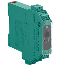
Technical data of the KFD2-RSH-1.2D.FL2-Y1
| Main Features | ||
|---|---|---|
| Signal type | Digital output | |
|
Parameters related to functional safety |
||
| Safety Integrity Level (SIL) | SIL 3 | |
| Systematic Capabilities (SC) | SC 3 | |
| Performance Level (PL) | PL e | |
|
Supply |
||
| Connection | Power bus or terminals 14+, 15- | |
| Nominal voltage | 19...26.4 V DC | |
| Input current | Max 35mA at 24VDC, max 44mA at 19VDC, with internal fault detection enabled | |
| Power consumption | < 1.7 W including digital input power consumption, see derating curves. | |
|
Entrance |
||
| Connection side | control side | |
| Connection | terminals 7+, 8- | |
| Pulse/pause ratio |
min. 150 ms/min. 150 ms with internal fault detection disabled min. 1 sec/min. 1 sec with internal fault detection enabled |
|
| Test pulse length | Max 2 ms from DO card | |
| Signal level |
0-signal: -5...5 VDC 1-signal: 20.5...26.4 VDC |
|
| Rated current |
0-signal: typical 1.6 mA at 1.5 VDC; typical 8 mA at 3 VDC (DO card maximum leakage current) 1-signal: ≥ 36 mA (minimum load current of DO card) |
|
| Inrush current | < 200 mA after 100 µs | |
|
Exit |
||
| Connection side | side of the field | |
| Connection |
external voltage: terminals 4+, 5+, 2- load: terminals 6, 3 |
|
| Connected voltage | 8...60 V DC | |
| Power dissipation | < 3.3W at 5A, see derating curves | |
| Contact loading | 30 VDC / 5 A resistive load, see derating curves | |
| Minimum switching current | 10 mA | |
| Mechanical life | 5 x 10 6 switching cycles | |
| Line fault detection |
low voltage < 5 VDC, Minimum current: 10mA DC; Overload current: 2.2A DC (relay energized) open circuit: 8.2 kOhm; short circuit: 11 Ohm (load, relay de-energized) |
|
| Fuse rating |
2.5 A (included) Max 5V, Recommended maximum fuse utilization rate: 80%. |
|
|
Fault indication output |
||
| Connection | terminals 10, 11 | |
| Contact loading | 30VDC/0.5A resistive load | |
| Reaction time | < 2 s | |
| Mechanical life | 10 5 switching cycles | |
|
Transfer characteristics |
||
| Switching frequency |
< 3 Hz with internal fault detection disabled < 0.5 Hz with internal fault detection enabled |
|
|
Galvanic isolation |
||
| Input/Power Supply | Basic insulation according to IEC/EN 61010-1, rated insulation voltage 60 V eff. | |
| Fault indication input/output | Basic insulation according to IEC/EN 61010-1, rated insulation voltage 30 V eff. | |
| Output/other circuits | reinforced insulation according to IEC/EN 61010-1, rated insulation voltage 300 V eff. | |
|
Indicators/settings |
||
| Display elements | LEDs | |
| Controls | DIP switch | |
| Configuration | via DIP switches | |
| Marking | marking space at the front | |
|
Compliance with the directive |
||
| Electromagnetic compatibility |
|
|
|
|
Directive 2014/30/EU | EN 61326-1:2013 (industrial premises) |
| Machinery Directive |
|
|
|
|
Directive 2006/42/EU | EN 62061:2005+AC:2010+A1:2013+A2:2015, EN/ISO 13849-1:2015 |
|
Correspondence |
||
| Electromagnetic compatibility | NE 21:2017, IEC/EN 61326-3-2:2018, EN 61326-3-1:2017 | |
| Degree of protection | IEC 60529:2013 | |
| Protection against electric shock | EN 61010-1:2010 | |
|
Environmental conditions |
||
| Ambient temperature |
-20 ... 60 °C (-4 ... 140 °F) Observe the derating temperature range, see Derating section. |
|
|
Mechanical characteristics |
||
| Degree of protection | IP20 | |
| Connection | screw terminals | |
| weight | approx. 142 g | |
| Dimensions | 20 x 119 x 115 mm (0.8 x 4.7 x 4.5 in) (W x H x D), case type B2 | |
| Installation | on a 35 mm DIN mounting rail in accordance with EN 60715:2001 | |
|
Data for use in hazardous areas |
||
| Certificate | PF 17 CERT 4305 X | |
|
|
Marking |
 II 3G Ex nC ec IIC T4 Gc [device in zone 2] II 3G Ex nC ec IIC T4 Gc [device in zone 2]
|
| Compliance with the directive |
|
|
|
|
Directive 2014/34/EU | EN 60079-0:2012+A11:2013, EN 60079-7:2015, EN 60079-15:2010 |